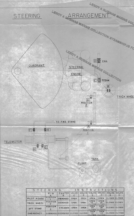
Steering Instructions to help crew operate gear in an emergency.
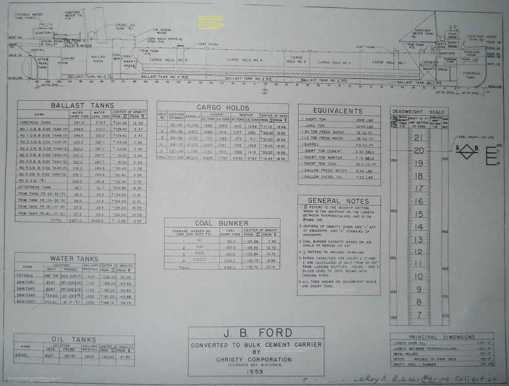
Dimensions:
Length Over All 440 feet
Length of Keel 420 feet
Beam 50 feet
Depth 28 feet
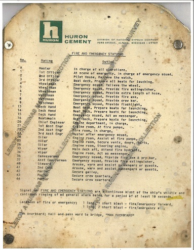
This is a list of all crew positions on the J. B. Ford when she sailed. Each position is crew’s title and duties in the event of a fire or emergency drill.
Engine:
Triple Expansion Reciprocating
Shaft Horsepower 1,500
Diameter of cylinders
High Pressure 22 inches
Intermediate 35 inches
Low Pressure 58 inches
Length of Stroke 40 inches
Self-unloading diesel engine:
Engine Mfg. by NORDBERG
ORDER NO. 9040-0617
MODEL FS-136-HSC
BORE 13 1/2″ STROKE 16 1/2″ RPM 514 BHP 1450
SUPAIR THERMAL ENGINE
MILLER SUPERCHARGEING SYSTEM
INLINE SIX CYLINDER
YEAR 1959
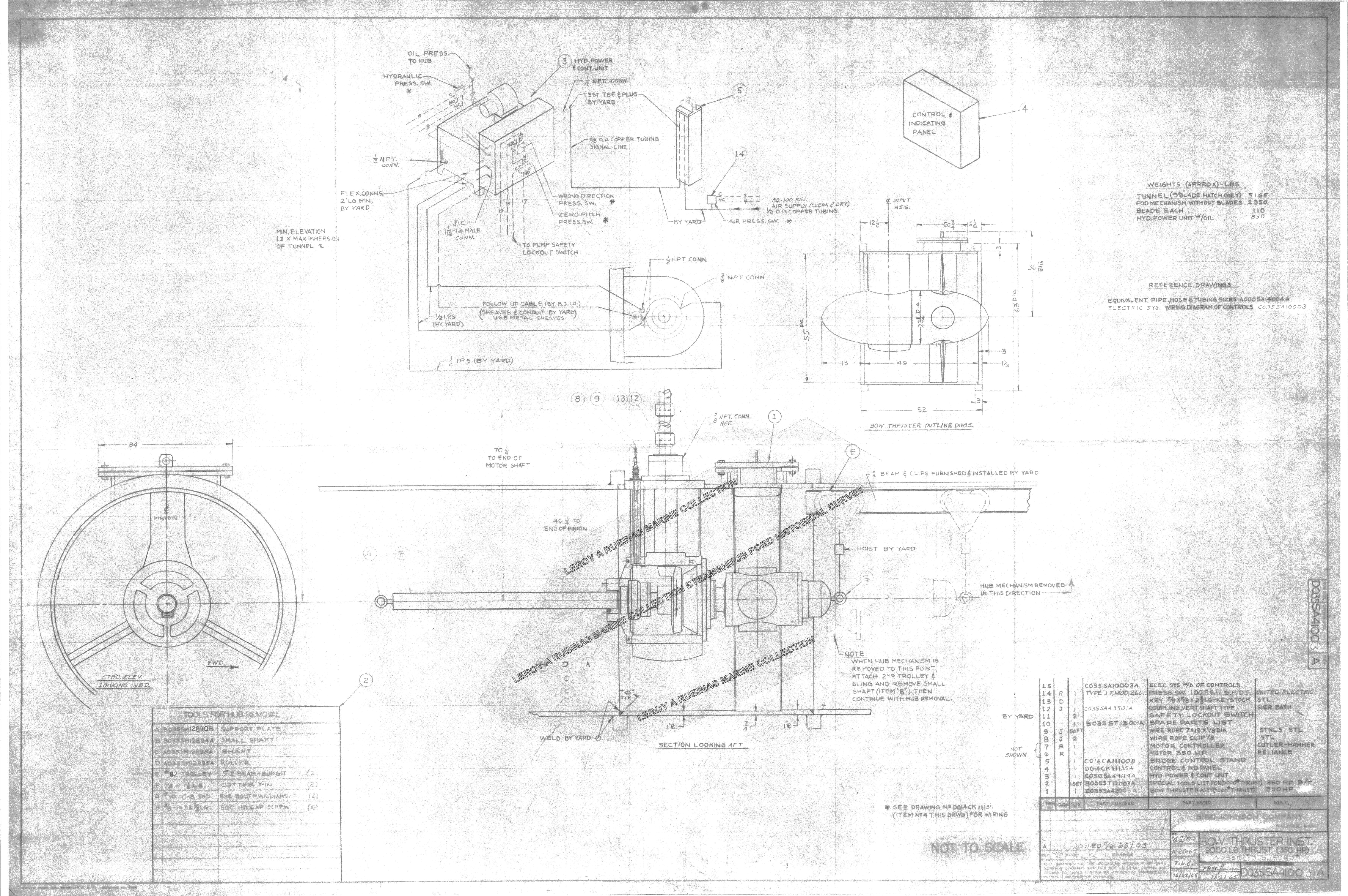
Tunnel Thruster:
Bird-Johnson 350 H. P. 9000 lbs. of thrust
Installed Winter layup 1965- 1966
Bow Thruster Drawing
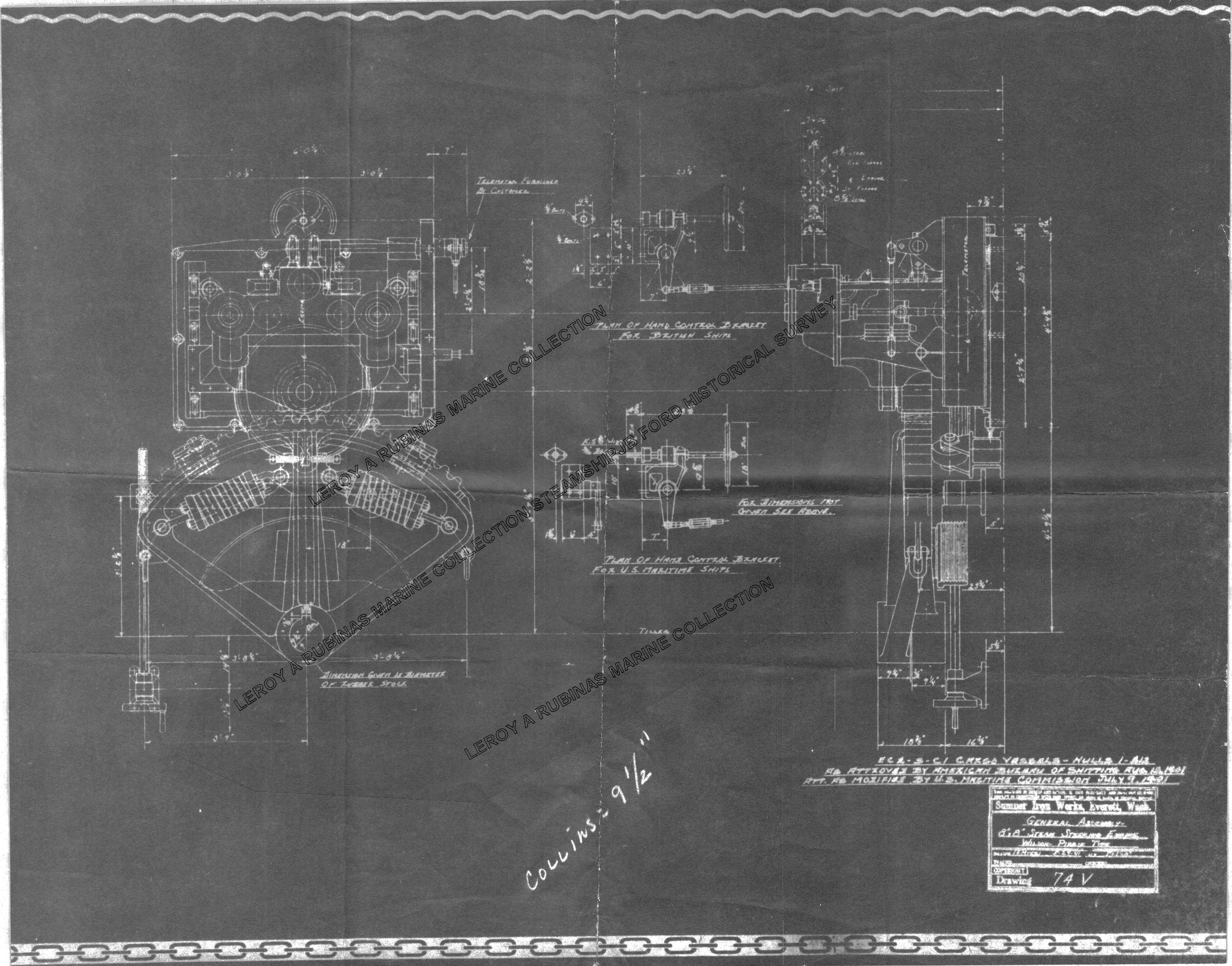
Steering Gear:
The Current Steering Gear was installed on the ship in 1959 during conversion
The unit weighs 7000lbs for the engine and slightly more than 7000lbs for the quadrant
The steering gear was one of many built for World War 2 cargo ships
Built in Seattle, WA.
steering gear July 9, 1941 US Maritime Com. Seattle , WA drawing
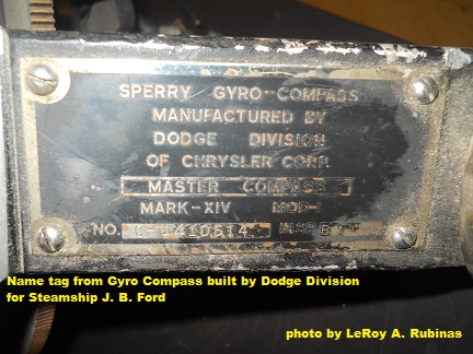
Gyro Compass
Sperry Gyro-Compass Mfg. Dodge Division of Chrysler Corp. Mark- XIV
The above Gyro-Compass was a model widely used on WW2 Era Vessels.
The S.S. J. B. Ford was fitted with Dodge products.
Tonnage as Edwin F. Holmes
4787 gross 3517 net
Tonnage as E. C. Collins
4132 gross 3001 net
Tonnage as J. B. Ford
4368 gross 3199 net
Official Number
200666
Hull Number
329
Cargo capacity in 1904
7,000 tons of iron ore
7,500 tons of coal
draft 18 feet for both cargos
Cargo capacity in 1959
7,400 tons of cement
draft 20 feet 1 inch
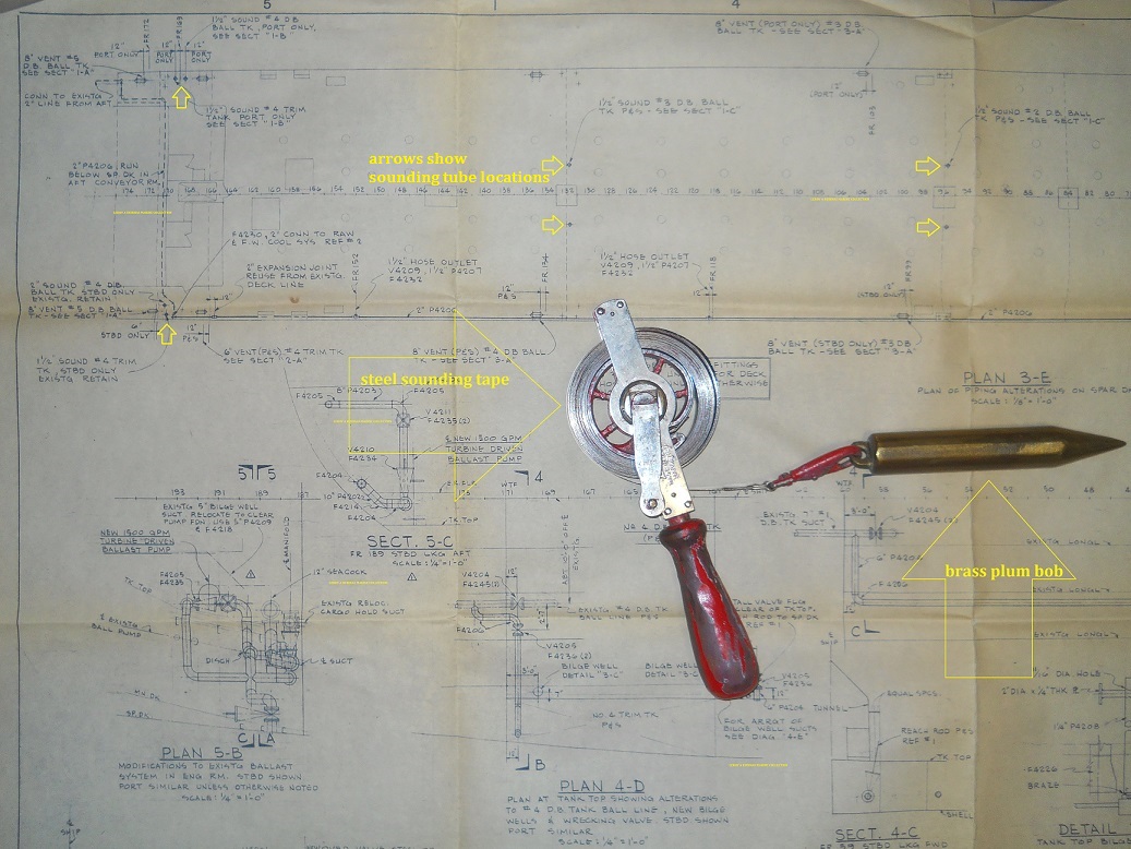
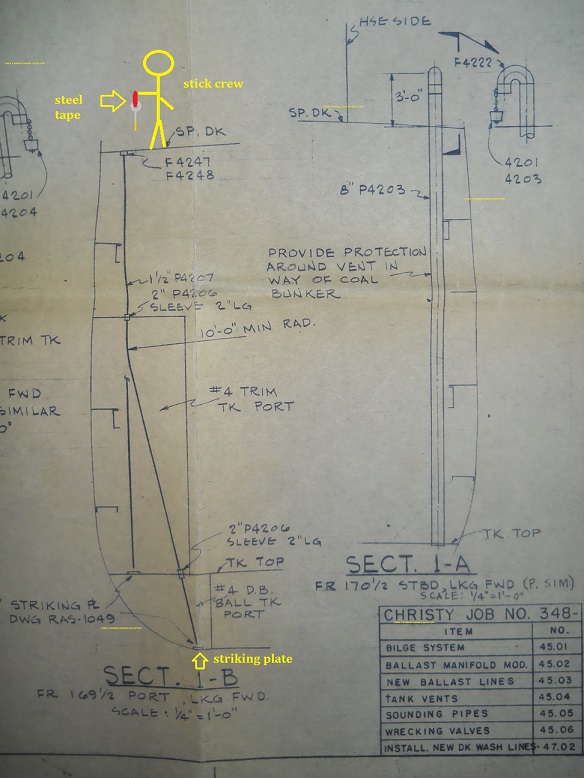
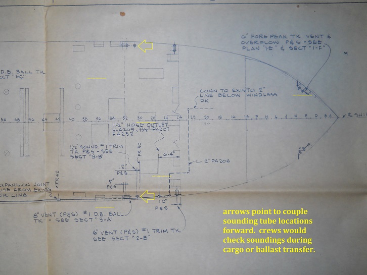
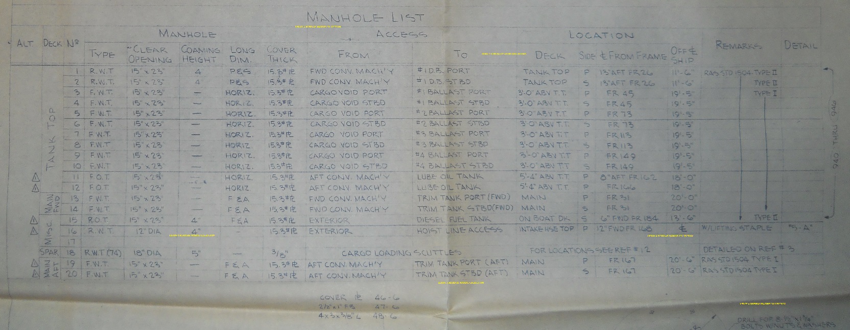
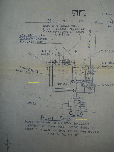
Ballast Manholes & Sounding tube details
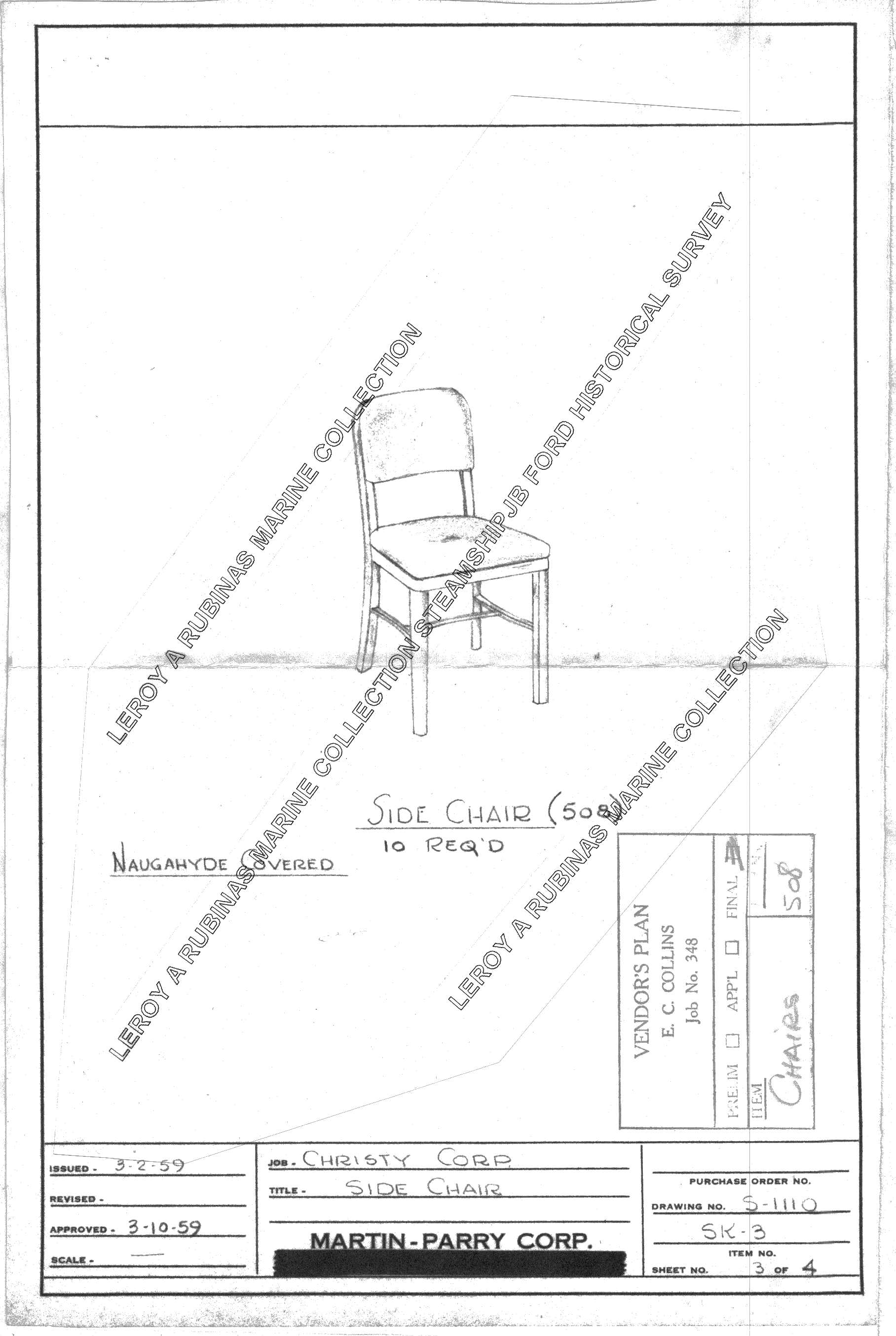
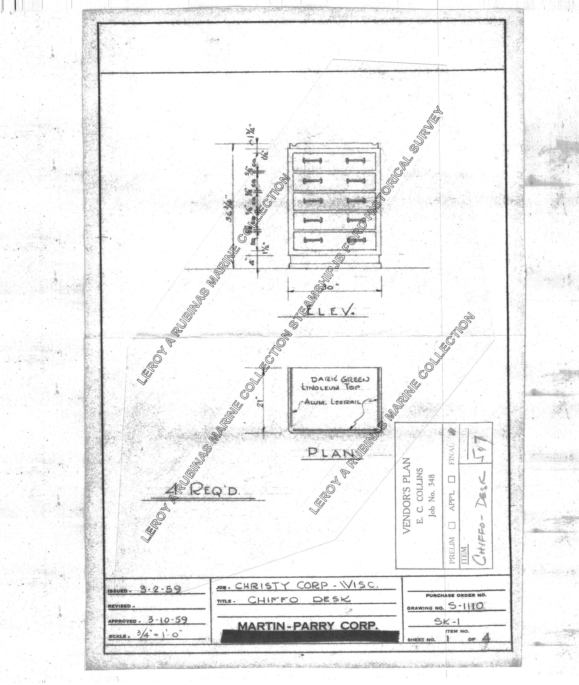
Pictured plans of Ballast system from 1958. Also a steel tape with brass plum bob. Steel tapes would be used by crew to see the liquid level in any tank. For water tanks a water detecting paste would be added to the tape approximately where the guessed level should be.In this view a stick crew is holding a steel tape. This person would removed the 1-1/2″ plug, add water detecting paste to the plum bob or guessed level of the tank. When the plum bob is lowed down the tube a distinct strike is heard when it taps the plate. The tape is slowly reeled back up until a level is seen. The level in inches is noted. When two soundings show the identical level, then this is marked down on record.This view shows a couple more sounding locations up forward. The crew would normally take soundings during ballast and cargo transfer.Man hole covers for various tanks were installed to allow periodic tank inspections or cleanings. In today’s world this would require a confined space permit and gas free test before allowing human access.In these old drawings back in 1958, a new steam driven turbine ballast pump was added in addition to the 1904 vintage reciprocating pumps.jbford chairsjbford chest of drawers